


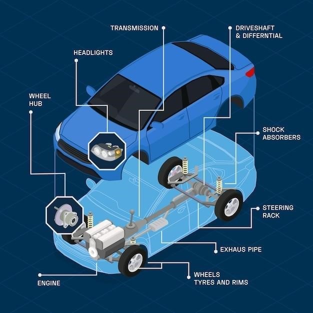
A manual transmission parts diagram is a visual representation of the different parts and their placement within the transmission system. This diagram helps you identify and locate specific components, making it easier to diagnose problems or find the right part for repair or replacement.
Introduction
A manual transmission, often referred to as a stick shift, is a gearbox that allows the driver to select from various gear ratios when driving the car. Lower gear ratios provide more torque but slower speeds, whereas higher gear ratios provide less torque but faster speeds. Because different gear ratios are referred to as speeds, a six-speed manual transmission has six forward gear ratios. The driver manually shifts the transmission by moving a gear lever, which engages different gears within the transmission.
Manual transmissions offer a level of control and engagement that automatic transmissions simply cannot match. Drivers can fine-tune their driving experience by selecting the appropriate gear for different driving conditions, such as accelerating from a standstill, climbing hills, or maintaining a consistent speed on the highway. This level of control is particularly appreciated by enthusiasts and drivers who enjoy a more involved driving experience.
A manual transmission parts diagram is a visual representation of the internal components and systems that make up a manual transmission. It provides a detailed illustration of how the gears, shafts, and other parts are arranged and interact with each other to transfer power from the engine to the wheels. This diagram is a valuable tool for understanding the workings of a manual transmission, diagnosing problems, and identifying specific parts for repair or replacement.
Clutch
The clutch is a vital component in a manual transmission system, acting as the interface between the engine and the transmission. Its primary function is to engage and disengage the flow of power from the engine to the transmission, allowing for smooth gear changes without jolting the drivetrain. The clutch consists of several key parts, each playing a crucial role in its operation.
The clutch pedal, operated by the driver’s foot, is connected to the clutch hydraulic system. When the pedal is pressed, the hydraulic system activates the clutch release bearing, which in turn pushes against the clutch pressure plate. This pressure plate, typically spring-loaded, compresses the clutch disc against the flywheel. The clutch disc, sandwiched between the flywheel and pressure plate, has friction material on both sides, allowing it to slip when the clutch is disengaged.
When the clutch pedal is released, the pressure plate forces the clutch disc to engage with the flywheel, transferring power from the engine to the transmission. The clutch disc’s friction material allows for a gradual engagement of power, minimizing the jolting effect on the drivetrain as the gears mesh. The clutch pedal’s position determines the amount of pressure applied to the clutch disc, enabling the driver to control the power transfer smoothly.
Flywheel
The flywheel is a heavy, rotating disc that is directly connected to the engine’s crankshaft. It plays a crucial role in smoothing out the engine’s power delivery and maintaining a consistent rotational speed. The flywheel’s inertia, its resistance to changes in motion, helps to absorb the fluctuations in engine torque, preventing sudden jolts and vibrations that would be transmitted to the drivetrain.
In a manual transmission system, the flywheel serves as the interface between the engine and the clutch. The clutch disc is pressed against the flywheel’s friction surface, allowing power to be transferred to the transmission. The flywheel’s large mass and inertia help to maintain a consistent rotational speed, even when the engine is under heavy load or when the clutch is engaged and disengaged. This smooths out the power delivery and helps to prevent stalling, particularly during acceleration or when starting the vehicle from a standstill.
The flywheel also plays a role in starting the engine. The starter motor engages a ring gear on the flywheel, rotating it to initiate the combustion process. The flywheel’s mass helps to store energy and sustain the engine’s rotation until it reaches a self-sustaining speed. As the engine runs, the flywheel continues to store energy, providing a buffer against sudden changes in torque and ensuring a smooth and consistent power delivery to the transmission.
Input Shaft
The input shaft is the first component in the transmission that receives power from the engine. It extends from the transmission’s front face, directly connecting to the clutch disc. The input shaft is responsible for transmitting the engine’s rotational power to the transmission’s internal gearset. It acts as a conduit, carrying the torque from the engine to the gears that will ultimately transfer it to the output shaft and the wheels.
The input shaft is typically splined, which means it has a series of grooves along its length. These splines engage with the clutch disc’s splines, creating a secure connection that allows for smooth power transfer. The input shaft is also often hollow, allowing the output shaft to pass through its center. This arrangement is common in many transmission designs and simplifies the internal layout of the transmission, minimizing the overall size and weight.
The input shaft is a critical component in the transmission system, as it connects the engine to the rest of the drivetrain. Its role is to transmit power efficiently and reliably, ensuring that the engine’s torque is transferred to the wheels smoothly. The input shaft’s design and construction are crucial for the proper functioning of the transmission, ensuring that the vehicle can accelerate, decelerate, and change gears smoothly.
Output Shaft
The output shaft is the final component in the transmission that delivers power to the drivetrain. It extends from the rear of the transmission, connecting to the driveshaft, which in turn transmits power to the rear axle or front wheels depending on the vehicle’s configuration. The output shaft is responsible for delivering the final gear ratio selected by the driver to the wheels, allowing the vehicle to move at the desired speed.
The output shaft is typically splined, similar to the input shaft, to engage with the driveshaft’s splines, ensuring a secure and smooth power transfer. The output shaft’s design also accommodates the various gears that are connected to it, allowing for different gear ratios to be selected by the driver. These gears are typically mounted on bearings, allowing them to rotate freely and efficiently.
The output shaft’s primary role is to transfer the selected gear ratio’s torque from the transmission to the driveshaft. This allows the vehicle to move at the desired speed and acceleration, providing the driver with control over the vehicle’s performance. The output shaft’s strength and durability are essential for reliable operation, ensuring that the transmission can handle the stress and torque generated by the engine and the drivetrain.
Gear Selector
The gear selector is a crucial component in a manual transmission, acting as the interface between the driver and the transmission’s internal gear selection mechanism. It is typically located on the transmission’s side or top, with a lever that the driver manipulates to engage different gears. The gear selector’s primary function is to allow the driver to choose the desired gear ratio, enabling the vehicle to move at different speeds and with varying levels of torque.
Inside the transmission, the gear selector lever is connected to a series of rods, forks, and sliding collars. These components work together to engage the appropriate gear within the transmission based on the driver’s selection. When the driver moves the gear selector lever, it activates a mechanism that shifts the collars, which in turn engage the desired gear on the output shaft. The gear selector ensures that the selected gear is properly engaged, providing a smooth and reliable power transfer to the drivetrain.
The gear selector is a critical component in the manual transmission system, enabling the driver to control the vehicle’s speed and power delivery. Its design must be robust and precise, ensuring that the driver’s selections are accurately translated into gear changes within the transmission. The gear selector’s operation is essential for the smooth and efficient functioning of a manual transmission, allowing the driver to experience the engagement and control that comes with manual shifting.
Synchromesh Gears
Synchromesh gears are a key component in modern manual transmissions, designed to facilitate smooth and precise gear changes. They operate by synchronizing the speeds of the input and output shafts before the gears engage, minimizing the grinding and noise often associated with manual transmissions. The synchromesh system utilizes a set of cone-shaped synchronizer rings, which are connected to the gears on the output shaft. When the driver selects a gear, the corresponding synchronizer ring engages with the gear, applying friction to slow down or speed up the output shaft until it matches the speed of the input shaft.
This synchronization process is crucial for smooth gear changes. Without synchromesh gears, the driver would need to perfectly match the speeds of the input and output shafts manually, which is difficult to achieve in practice. Synchromesh gears allow the driver to shift gears quickly and easily, without the need for precise engine speed matching; This is especially beneficial during high-speed driving or when downshifting, where the speed difference between the input and output shafts can be significant.
Synchromesh gears are an essential part of modern manual transmissions, enhancing the driving experience by providing smoother and more efficient gear changes. They eliminate the need for precise engine speed matching, allowing drivers to shift gears quickly and effortlessly. Synchromesh gears contribute to the overall performance and reliability of manual transmissions, making them a popular choice for a wide range of vehicles.
Shift Lever
The shift lever, often referred to as the gearstick, is the driver’s interface with the manual transmission. It’s the physical component that allows the driver to select the desired gear ratio. Connected to the transmission’s internal gear selector mechanism, the shift lever translates the driver’s movements into actions within the transmission, enabling gear changes. The shift lever is typically located on the floor of the vehicle, although some older models may have a column-mounted shifter.
The shift lever’s design often includes a pattern of markings or gates, which guide the driver in selecting the correct gear. The most common shift pattern is a “H” configuration, with the gears arranged in a vertical pattern, with reverse at the top or bottom, depending on the vehicle. The shift lever operates a linkage system that connects to the gear selector within the transmission. This linkage system translates the lever’s movement into a corresponding action within the transmission, engaging the desired gear.
The shift lever is a critical component of the manual transmission system. It allows the driver to control the vehicle’s power delivery and speed, enabling them to optimize performance and fuel efficiency in various driving conditions. The shift lever’s design and operation are crucial for the overall driving experience, providing a direct and engaging connection between the driver and the vehicle’s powertrain.
Transmission Case
The transmission case, sometimes referred to as the gearbox housing, is the primary structural component of a manual transmission. It serves as a robust enclosure that houses all the internal components, protecting them from external elements and providing a rigid framework for their operation. The transmission case is typically made from cast iron or aluminum, depending on the specific design and application.
The transmission case is designed to withstand the high forces and stresses generated during gear changes and power transfer. It features a series of internal passages and cavities that allow for the circulation of lubricating oil, ensuring smooth operation of the gears and bearings. The case also incorporates mounting points for the transmission to the engine, as well as external connections for the shift linkage and other ancillary components.
The transmission case is a critical component for the overall functionality and durability of the manual transmission. It provides essential protection and support for the internal mechanisms, allowing them to operate efficiently and reliably. The case’s design and construction are crucial for ensuring the transmission’s long-term performance and preventing damage or failure.